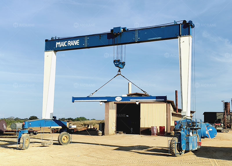
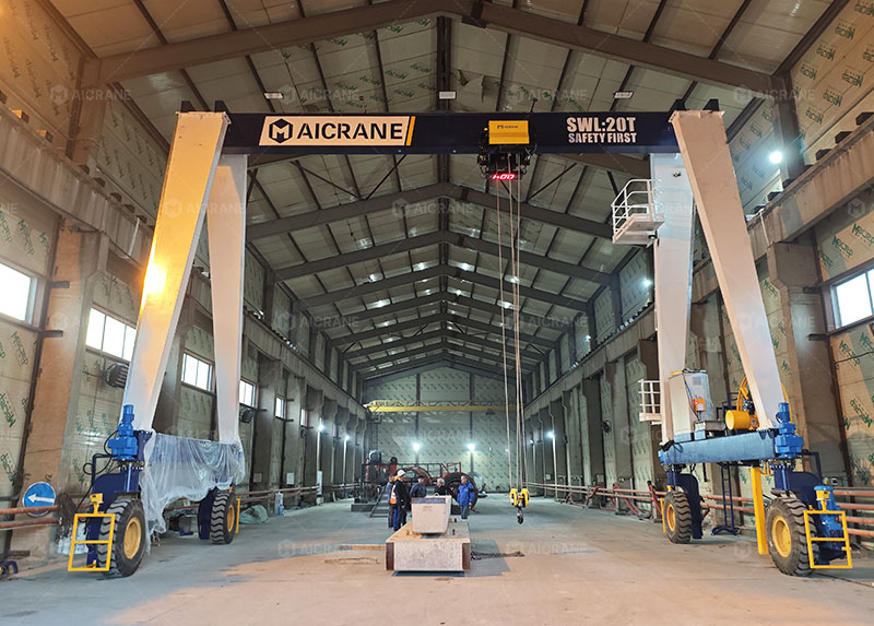
A Rubber Tyred Gantry (RTG) crane is a mobile gantry crane used primarily in container terminals, railway yards, and heavy industrial yards to stack and transfer containers or large structural components. Unlike Rail Mounted Gantry (RMG) cranes, which are restricted to fixed steel tracks, the RTG relies on heavy-duty rubber tyres. This design provides the crane with multi-directional mobility and the ability to transfer between different storage lanes (yards).
To move a structure that typically weighs between 120 and 200 metric tonnes (unloaded) and carries payloads of up to 40 to 50 tonnes, the travel system of an RTG gantry crane must integrate robust structural design, precise electrical drive control, and heavy-duty hydraulics. This article details the mechanical, electrical, and control systems that govern how an RTG travels, steers, and maintains alignment.
1. Structural Foundation: Bogies and Equalizer Beams
The massive weight of the RTG and its load cannot be placed directly onto rigid wheel axles. Doing so would cause uneven wheel loads, rapid tyre wear, and structural damage whenever the crane encounters minor ground unevenness.
To solve this, RTGs use a system of equalizer beams and bogies (also called sill beams or wheel groups).
- Wheel Configurations: An RTG typically travels on 8, 12, or 16 tyres. The wheels are grouped into bogies at each of the crane’s four corner sills. A common configuration is the 8-wheel RTG (two wheels per corner) or the 16-wheel RTG (four wheels per corner).
- Load Distribution: The equalizer beams act as mechanical levers (pivots). When one tyre rolls over a small depression or bump in the concrete runway, the equalizer beam swivels slightly. This maintains constant contact between all tyres and the ground, distributing the total load evenly across all wheel assemblies and protecting the main steel structure from torsional stress.
2. Power Generation and Drive Systems
The movement of the mobile gantry crane along its runway (referred to as the “gantry travel” or “long travel”) is powered by either onboard diesel generators or an external electrical grid connection.
Power Sources
- Diesel-Generator Set (Genset): A large diesel engine coupled to an alternator is mounted on the upper girder or sill beam. It generates AC power (typically 400V to 480V at 50Hz/60Hz) which is distributed to the drive motors.
- E-RTG (Electric RTG): Modern terminals increasingly use electrified RTGs to reduce emissions. These draw power from the grid via continuous conductor bars (busbars) running alongside the stack lane, or through motorized cable reels.
Drive Train Mechanics
The power from the electrical system is converted into physical motion at the wheels through a dedicated drive train on each motorized bogie:
- Variable Frequency Drives (VFDs): The speed of the travel motors is controlled by variable frequency drives. VFDs allow for smooth acceleration and deceleration, preventing the crane from jerking, which could cause container sway or mechanical fatigue.
- Electric Motors: Heavy-duty, totally enclosed fan-cooled (TEFC) AC induction motors are mounted on the driven bogies. Typically, 50% of the wheels on an RTG are driven (active wheels), while the remaining 50% are idle (passive wheels).
- Reduction Gearboxes: The high-speed rotation of the AC motor is converted into high-torque, low-speed rotation through multi-stage helical or planetary gearboxes directly coupled to the wheel shafts.
- Chain Drives vs. Direct Drives: Older RTG models often utilized heavy-duty roller chains to transmit torque from the gearbox to the wheels. Modern designs prefer direct-drive configurations (shaft-mounted gearboxes) because they require less maintenance and offer higher mechanical efficiency.
3. Steering Mechanisms and Operational Modes
The defining operational advantage of an RTG over an RMG crane is its ability to steer. To change stack lanes or navigate around obstacles, the wheel groups must rotate relative to the crane’s portal frame.
Each corner wheel group is mounted on a large-diameter slewing bearing (turntable). Rotation of these turntables is driven by either hydraulic cylinders or electric slewing gearmotors.
Primary Travel and Steering Modes
By coordinating the angles of all wheel groups, an RTG can execute several distinct travel maneuvers:
- Straight Line (Gantry) Travel: All wheels are locked parallel to the main sill beams. The crane moves forward and backward along the stack lane.
- 90-Degree Cross-Travel (Crab Steering): All wheel groups are turned exactly 90 degrees perpendicular to the sill beams. This allows the RTG to drive sideways, moving from one container bay or stack lane to an adjacent one.
- Carousel / Pivot Turn: The wheels are turned at tangent angles relative to the center point of the crane’s footprint. When power is applied, the crane rotates 360 degrees on its own axis. This is highly useful for orienting the crane in tight maintenance areas.
- Coordinated / Skew Steering: The wheels are turned at slight, varying angles to allow the crane to travel along a curved path or to correct minor orientation errors relative to the lane.
During the transition between steering modes (e.g., changing from straight travel to 90-degree crab steering), the gantry crane must come to a complete stop. Jacking systems are sometimes used to slightly relieve tyre pressure during rotation to prevent excessive friction and tyre shredding on the concrete surface.
4. Auto-Steering and Path Correction Systems
Because rubber tyres are flexible and subject to uneven deflection, and because yard runways are rarely perfectly level, an RTG will naturally drift or skew over long distances. Left uncorrected, this drift can cause the crane to collide with container stacks or drive off the designated runway.
To maintain a straight path without requiring constant manual adjustment by the operator, modern RTGs are equipped with Automatic Gantry Steering Systems (AGSS).
Feedback Loop and Correction Control
The AGSS continuously measures the crane’s deviation from a reference path using one or more of the following technologies:
- DGPS (Differential Global Positioning System): Dual GPS antennas mounted on opposite sides of the crane track its position and heading with centimeter-level accuracy.
- Laser Scanners / 2D Cameras: Sensors detect painted lines or physical magnetic markers embedded in the runway surface.
- Inductive Wire Guidance: Antenna coils on the crane detect an electromagnetic field generated by an energized wire buried in the center of the runway.
Differential Speed Control
When the controller (usually a Programmable Logic Controller, or PLC) detects a deviation or a skew angle (where one side of the crane is slightly ahead of the other), it does not physically turn the wheels while driving. Instead, it applies differential speed control to the drive motors.
If the left side of the crane is drifting forward, the VFDs will slightly reduce the speed of the left-side motors or increase the speed of the right-side motors until the crane is square and centered on the path.
5. Braking and Safety Systems
Stopping a moving mass of over 200 tonnes safely requires a highly reliable and redundant braking infrastructure.
- Dynamic Braking: During normal operation, deceleration is handled electrically by the VFDs. When the operator commands a stop, the drives slow down the motors electrically, acting as generators. The resulting electrical energy is dissipated through dynamic braking resistor banks or fed back into the grid (in E-RTG configurations).
- Holding / Parking Brakes: Electromagnetic or electro-hydraulic thrust disc brakes are mounted on the high-speed shaft of each travel gearbox. When the crane comes to a stop, or if power is lost, these brakes automatically engage via heavy-duty springs to lock the wheels.
- Storm Anchors and Rail Clamps: Because RTGs have high wind profiles, extreme wind conditions can cause them to slide. When parked during storms, physical tie-downs or wheel chocks are applied to secure the crane to the ground.
- Collision Prevention: Laser rangefinders, ultrasonic sensors, and physical safety bumpers are mounted on the leading edges of the bogies. If an obstacle (such as a utility vehicle or a ground worker) is detected in the travel path, the PLC initiates an emergency stop, immediately cutting power to the drives and engaging the mechanical brakes.
Summary of Travel Specifications
| Component | Common Engineering Specification |
|---|---|
| Gantry Travel Speed | 45 to 135 meters per minute (m/min) depending on yard layout |
| Steering Time (0 to 90 degrees) | 20 to 45 seconds |
| Maximum Gradient | Up to 1% to 2% slope handling capability |
| Tyre Pressure | Typically 8.0 to 10.0 bar (116 to 145 psi) |
| Wheels Powered | Usually 50% of total wheels (e.g., 4 out of 8, or 8 out of 16) |
Through this combination of balanced mechanical suspension, precise motor speed synchronization, variable wheel alignment, and automatic path correction, the modern rubber tyred gantry crane achieves the structural stability of a heavy machine alongside the spatial flexibility required in high-throughput logistics terminals.